Sheep grazing on solar farms is no longer unusual in the UK. As agrivoltaics has moved from concept to mainstream practice, graziers, site operators, and EPC contractors are increasingly navigating the same transition: how to introduce livestock to a site in a way that captures the operational and ESG benefits without creating new infrastructure risks. Most of the guidance available focuses on the farming side of that arrangement: stocking rates, grazing agreements, welfare, weed control. Very little of it addresses the electrical infrastructure risk with any precision. This guide does.
The specific risk we are discussing is livestock access to solar inverter cable runs. It is one of the most preventable O&M liability points on any agricultural solar site. It is also consistently underspecified. More often than not, the question of who provides protection is left unanswered until after commissioning, when it is more disruptive and more expensive to address. The InverShield Mesh Box, available exclusively from CMT Group, is purpose-built to close that gap.
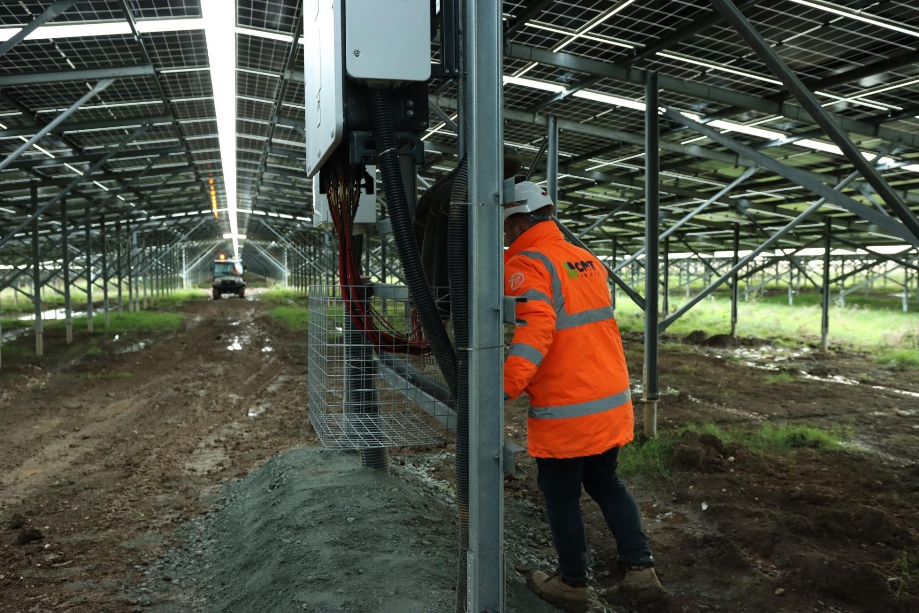
The Agrivoltaics Context: Why More UK Solar Sites Now Have Livestock
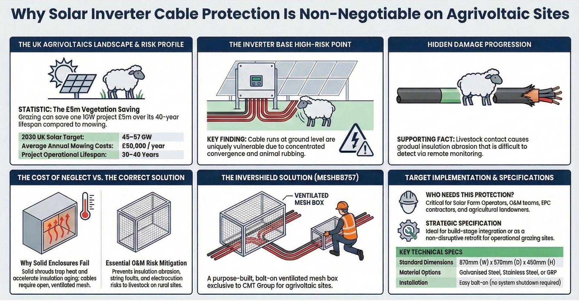
The economics of sheep grazing on solar farms are compelling for both sides. Solar operators are under pressure to reduce operational costs across project lifetimes that run to four decades. Mechanical mowing and spraying around panel arrays is expensive, produces carbon emissions that sit awkwardly alongside a renewable energy narrative, and is difficult to carry out safely around fixed infrastructure. Sheep provide continuous, low-impact vegetation control. On some UK projects the cumulative cost saving is measured in millions of pounds over the project's life.
Sheep are also particularly well matched to solar farm conditions. Unlike cattle, which can push against structural components, or goats, which are prone to climbing, sheep are consistent grazers that move between panel rows without causing structural damage. Research published in Applied Animal Behaviour Science found that sheep with access to solar panels actually graze more actively than those on open pasture, partly because the panels provide shade and shelter during hotter periods.
For farmers, a solar grazing arrangement can provide a reliable grazing block in summer, a paid vegetation management service contract, or simply a way to keep land in active agricultural use while a long-term energy project occupies it. For landowners, dual use helps maintain the agricultural character of land under solar lease, which can be a planning and valuation consideration.
The result is that solar grazing is increasingly designed in from the start of new UK projects rather than added retrospectively. That creates a growing number of UK solar sites where livestock access to electrical infrastructure is a day-one design consideration, and where the question of cable protection at inverter bases should be answered at the EPC stage, not discovered during the first O&M inspection after commissioning.
The Infrastructure Gap in the Agrivoltaics Debate
There is no shortage of guidance on the agricultural side of sheep grazing on solar farms. A good deal of attention has been given to stocking rates, grazing agreements, welfare requirements, suitable sheep breeds, and the commercial structures used between graziers and solar operators. This guidance is valuable. But it consistently underweights one practical question that falls firmly on the site operator's side: what happens to the electrical infrastructure at ground level once sheep are present?
The standard framing of livestock risk on solar sites focuses on panel damage. Sheep are generally accepted to pose low structural risk to elevated panel arrays, and this assessment is broadly correct. The panels themselves are inaccessible. The racking structure is robust. The risk is not there.
The risk is at the inverter base. And it is almost always treated as an afterthought. Guidance documents typically acknowledge it in a single line, noting that "physical barriers around sensitive equipment" are good practice, before moving on. What type of barrier? What specification? What are the thermal implications of getting it wrong? Who provides it, and when? These questions are rarely answered with any precision, which means the decision is deferred to a contractor or site manager who may have no clear brief for it.
"Physical barriers around sensitive equipment" is standard advice in solar grazing guidance. What type, what specification, and what the thermal implications of getting it wrong are: these questions are almost never answered. This guide answers them.
Why the Inverter Base Is Specifically the High-Risk Point
Not all ground-level electrical infrastructure on a solar site presents the same livestock risk. Underground cable runs in conduit are inaccessible. Inter-string wiring between panels is clipped to racking at height and not something sheep can meaningfully interact with. Substation compounds are typically fenced. But the inverter base is different in three specific ways.
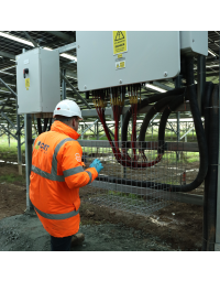
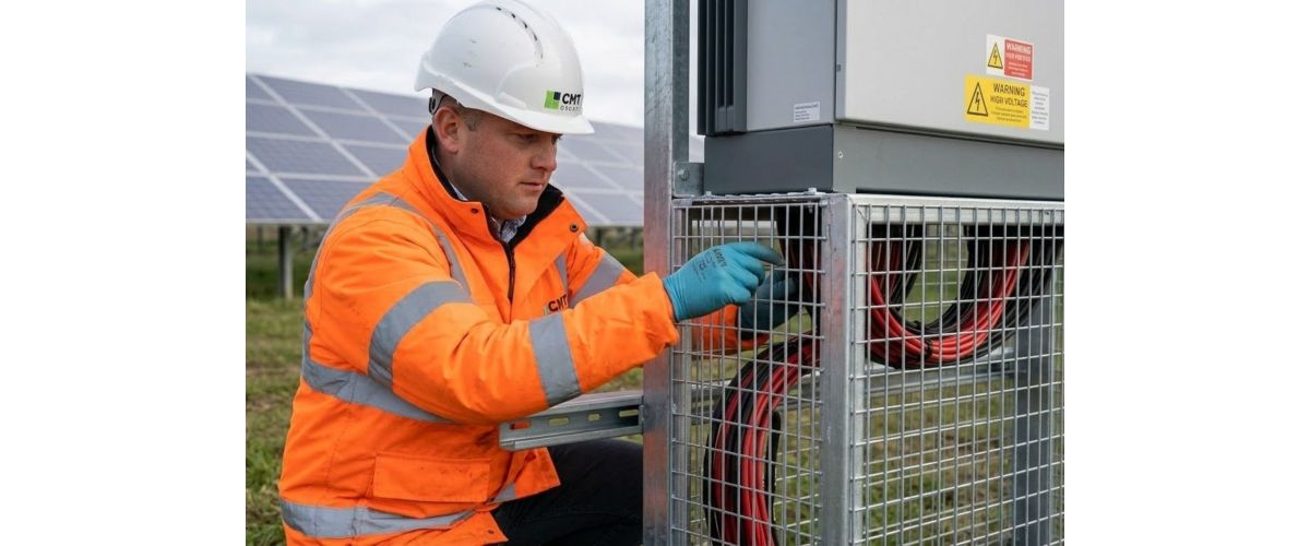
First, it is a point of cable convergence. Multiple string cable runs arrive at the inverter from across the array, dropping to ground level at the cabinet base before entering conduit. On many installations, this means a significant concentration of accessible cabling at a single, fixed location: not distributed along a cable route, but gathered at one spot.
Second, it is a fixed, predictable location that animals return to repeatedly. Inverter cabinets provide a rubbing surface. The base area offers shelter. And unlike a random point along a fence line, the inverter location does not change. Sheep that discover and investigate an inverter base in week one will return to it in week two, week ten, and month twelve.
Third, the damage tends to be gradual and difficult to detect remotely. A single instance of cable rubbing may not immediately present as a performance fault. Repeated contact over weeks and months produces progressive insulation wear, cable displacement from routing clips, and eventually either a fault code or a latent fault that presents unpredictably under load or in wet weather.
Standard solar O&M contracts include inspection of inverter cable runs for signs of animal interference as a specific check item. On non-grazing sites, this is precautionary. On sites where livestock have direct access to inverter bases without physical protection in place, it is a likely finding. The callout costs involved in investigating and remediating cable damage on a rural agricultural site substantially exceed the cost of prevention.
Why a Solid Enclosure Is the Wrong Answer, and What Matters Instead
When site operators or EPC contractors first address the inverter cable protection question, the instinctive answer is often a solid steel shroud or a repurposed site cabinet fitted around the cable run area. It is an understandable first response: the cables need to be enclosed, a steel box encloses them, problem solved. But this approach creates a secondary problem that is less visible and arguably more damaging over a long project life.
Solar inverter cable runs and junction connections generate heat in operation. Cable insulation, connectors, and associated components all have thermal operating ranges within which they perform as specified and maintain their rated service life. Elevated temperatures, even sustained rather than extreme, accelerate the ageing process. Insulation becomes brittle. Connector housings degrade. The rate of degradation is not linear; it compounds over time.
A sealed steel enclosure around an inverter cable run creates a confined air volume around heat-generating components. In summer, on a south-facing UK solar site, the internal temperature of a poorly ventilated enclosure can run significantly above ambient air temperature. Over months and years of operation, this thermal stress shortens the service life of the cable insulation.
The correct solution separates the two requirements. The barrier against animal contact must be physical and effective. The thermal environment around the cables must be maintained. The answer is a ventilated mesh construction: open enough to allow continuous passive airflow around the electrical components, but with a mesh aperture sized to prevent livestock access to the cables behind it.


The InverShield Mesh Box: Purpose-Built for This Application
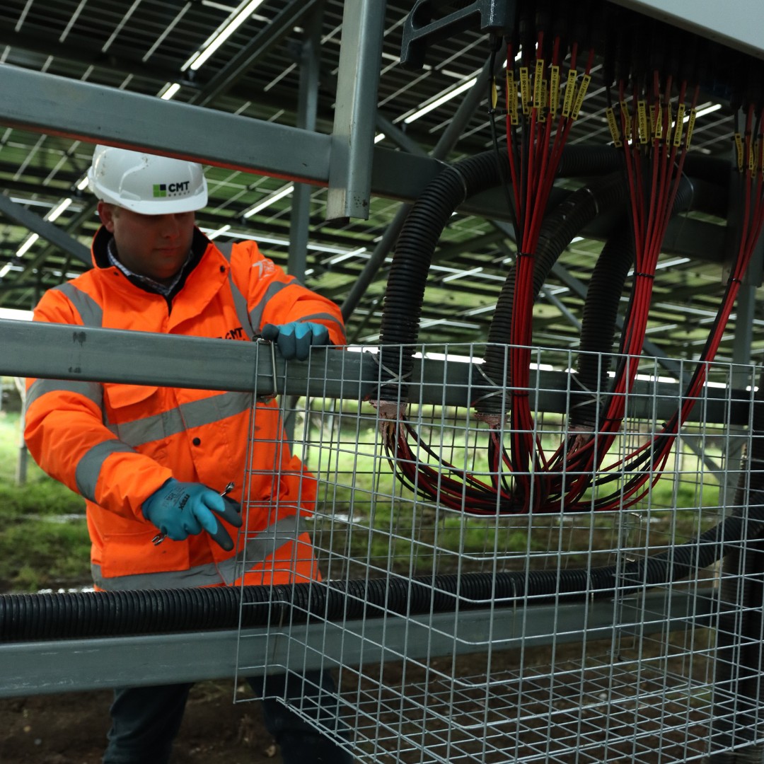
The InverShield Mesh Box is a ventilated mesh enclosure designed to fit around the inverter cable run and junction area, providing physical exclusion of livestock while maintaining the passive airflow that cable and junction components require. It is the only purpose-built UK product for this specific application, and it is exclusive to CMT Group.
The construction is galvanised or stainless steel mesh, with a GRP variant available for sites with specific requirements. Galvanised steel is the appropriate specification for the majority of UK agricultural solar installations. Stainless steel is recommended for coastal sites or locations with elevated salinity. The GRP option is electrically non-conductive, which can be relevant in certain installation contexts where the electrical safety case benefits from a non-conductive enclosure in proximity to live cable connections.
Finish options (powder coated or zinc coated) allow the enclosure to be specified to match site or client requirements. Standard dimensions are 870mm wide by 570mm deep with a 460mm back panel, covering the cable run configurations found on the majority of UK solar inverter installations. Custom sizes are available for any inverter model or routing layout, with no minimum order volume.
Installation is by bolt-on mounting, which means the enclosure attaches to existing inverter structure without welding or structural modification. For O&M teams retrofitting protection to sites already in operation, this keeps installation time and disruption to a minimum and does not require system shutdown.
When and How to Specify Inverter Cable Protection
The most cost-effective point to specify inverter cable protection is at the EPC build stage, before commissioning. At this point, the enclosures can be integrated into the inverter installation scope, access is straightforward, and there is no disruption to an operational system. It is also the point at which the question of who provides infrastructure protection can be clearly resolved, rather than left as an ambiguity in the grazing agreement.
Grazing guidance generally frames physical barriers around inverter equipment as the developer's responsibility. Leaving this undefined creates a common pattern: the grazier assumes it is provided, the site operator assumes it is in scope for someone else, and the question surfaces at the first O&M inspection rather than at the planning or commissioning stage.
For operational sites where grazing is being introduced retrospectively: retrofit installation is straightforward. The bolt-on method means the InverShield can be fitted around existing cable runs without a system shutdown and without modifying the inverter mounting.
Inverter Cable Protection: Specification Checklist
Map every inverter base where cable runs are accessible at or below 800mm from ground level.
Standard MESHB8757 dimensions cover most common configurations. Measure and note any non-standard layouts for custom sizing.
Galvanised for inland agricultural sites. Stainless for coastal or high-salinity locations. GRP where electrical non-conductivity is a requirement.
Solid shrouds restrict airflow. Any enclosure specification must confirm open mesh construction that maintains passive airflow around cable runs.
Document physical protection of inverter cable runs as a site operator obligation, not an item to be resolved by the grazier.
The InverShield installs around existing cable runs without structural modification or system downtime.
Include InverShield condition in routine site inspections: mesh integrity, mounting security, and no signs of animal interference within the enclosure.
InverShield Mesh Box: Specifications at a Glance
Frequently Asked Questions
Why are inverter cable runs more vulnerable than the rest of a solar array on a grazing site?
Panel arrays are elevated and structurally robust. Inter-string wiring is clipped to racking at height. But inverter cable runs drop to ground level at a fixed location where multiple cables converge, creating a concentration of accessible cabling at a single predictable spot that livestock will return to repeatedly. The damage is gradual and tends to accumulate over many months before triggering a fault.
Why is a solid steel enclosure the wrong answer for inverter cable protection?
A solid enclosure blocks animal access but restricts airflow around heat-generating cable runs and junction components. The resulting heat build-up elevates the ambient temperature around the cables, which accelerates insulation ageing over time. The correct answer is ventilated mesh: physically effective against animals, thermally neutral for the cables.
Who is responsible for providing inverter cable protection on a solar grazing site?
Physical protection of the site's electrical infrastructure is a site operator obligation, not something that falls to the grazier. The most effective approach is to specify it explicitly in the EPC scope at build stage. For sites where grazing is being introduced retrospectively, it should be treated as a site operator provision item in the grazing agreement from the outset, not a shared responsibility that ends up unresolved.
Can the InverShield Mesh Box be retrofitted to a site already in operation?
Yes. Its bolt-on installation method fits around existing cable runs without welding, structural modification to the inverter mounting, or system shutdown. Custom sizing is available for non-standard configurations, with no minimum order volume.
What materials and sizes are available, and how do I choose the right specification?
Galvanised steel is the standard specification for most UK agricultural solar sites. Stainless steel is the correct choice for coastal or elevated-salinity environments. GRP is available where electrical non-conductivity is a specific requirement. Custom dimensions are available on request with no minimum order. The CMT team can advise based on site location, inverter model, and exposure conditions.
Why buy inverter cable protection from CMT Group?
The InverShield Mesh Box is exclusive to CMT Group and not available from any other supplier in the UK. CMT is the UK's largest independent site equipment supplier, with over 11,000 trade customers, 100-plus FORS Silver vehicles covering 95% of UK postcodes, and accreditations including CHAS Elite, ISO 9001:2015, Constructionline Gold, Crown Commercial Service, and BSIF Registered Safety Supplier.